In metaIworking production there are two drivers for automated workpiece handling: Cost reduction by increasing the utilization degree of machine tools and the shortage of skilled workers.
At machining centers the automated loading and unloading of workpieces saves precious machining time and therefore increases OEE.
Up to now the positions of hydraulic clamping cylinders typically are monitored with two or three switching output position sensors. Or with volume counting sensors which measure the hydraulic liquid volume flowing into or from the cylinder.
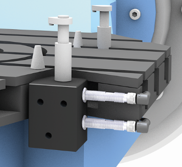
Inductive Sensors monitor the piston position of a clamping cylinder.
With the up to now existing solutions mainly fixed clamping positions can be detected. This is feasible if always the same type of workpieces are loaded to the milling centers.
To increase flexibility for the handling and production of a variety of workpieces the clamping concepts need to be more flexible with different clamping positions. Therefore position transducers with continuous signal output enable monitoring of variable clamping positions.
Recent progress in sensor technology enables such applications: Sonar sensor technology for liquid applications has significantly evolved and now realizes continuous position feedback also in hydraulic applications.
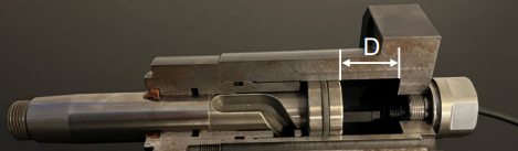
With a sonar / ultrasonic sensor principle the distance in the oil-filled area between piston and sensor is measured. Typical ranges for distance “D” are between 10 and 80 mm. Sensors with continuous position feedback (0..10 V, 4…20 mA, IO-Link,..) provide more information about the clamping status compared to binary switching sensors. This increases flexibility when machining different kinds of workpieces with frequent changes of production lots.
Sonar / ultrasonic position sensor for hydraulic cylinder applications
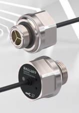
The sensor position information may be transmitted via short range inductive coupler solutions which combine power supply and signal transfer
Inductive couplers transfer electrical power and data without physical connector. This allows easy coupling and decoupling.
The combination of sensors and wireless communication over several meters like e.g. IO-Link Wireless opens possibilities to create flexible solutions. Link to IO-Link Wireless technology.
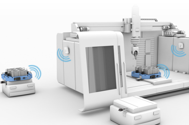
Automated workpiece handling at machine tools
For applications with integrated usage of AGVs the implementation of wireless technologies makes sense to create a flexible communication concept between the production and logistic modules
The clamping status of a workpiece on a palette is permanently monitored and sent to the control system via wireless transmission. So even during the exchange process of palettes in machining centers there is information about the clamping status of the workpiece.
Reliability of data transmission is a key feature for industrial applications. Another important point is the compatibility between both hard-wired topology and wireless solutions as it is expected that both will be implemented in parallel at industrial applications and will coexist.
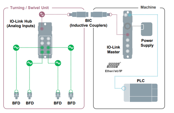
IO-Link Wireless and wired IO-Link topology:
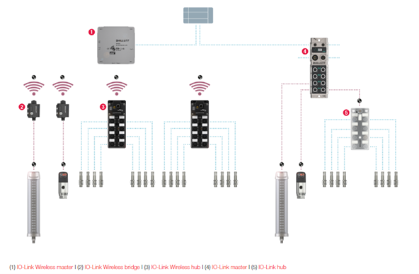
IO-Link Wireless and classical IO-Link
Signals of sensors with switching output are collected in a box with e.g. 8 inputs. For sensors with IO-Link interface a “IO-Link wireless bridge” may be used to transmit the data. IO-Link Wireless Devices.
The data are sent to a “IO-Link wireless master” which is configured like a wired “IO-Link master” IO-Link Wireless Network Blocks. With IO-Link Wireless a reliable solution for wireless data transmission is available. Advantages are in easier planning and installation, flexible integration of sensors and actuators, facilitated upgrade of existing systems and installations. Link